Innovative Valve Technologies
Yeary Controls
Chicago, IL
312.335.1012
Yeary Controls "Varying Area Diffuser"
Varying Area Diffuser (VAD) Technology
Our inovative, Varying Area Diffuser (VAD) technology allows for simpler, more economical on-off valves to be used in many control applications.
VAD Benefits
With a VAD installed downstream of a manually adjustable, or automated valve, it is possible to get exceptional control and significant reductions in cavitation and noise. By taking 85% of the system pressure drop through the VAD, wear and tear on the throttling valve's trim is significantly reduced, allowing for less expensive and simpler valves, like gate, butterfly and ball valves to be used for severe control applications.
How It Works
The force generated by the VAD's spring causes the moving cylinder to align its diffuser holes with the holes in the fixed outer cylinder so as to maintain a constant 15, to 20 psi pressure drop across the adjustable valve. Because the area of all of the holes vary in unison,a VAD maintains a 0.99 FL over its entire range of control. Because the total stroke of the device is only equal to the diameter of one of the diffuser holes it responds instantly to upsets in the pressure control loop, significantly reducing the need for controller re-tunings, therefore creates less downtime and faster re-tuning.


The "VAD" In Motion
The VAD is an automatic, force-balance, differential pressure regulating device.
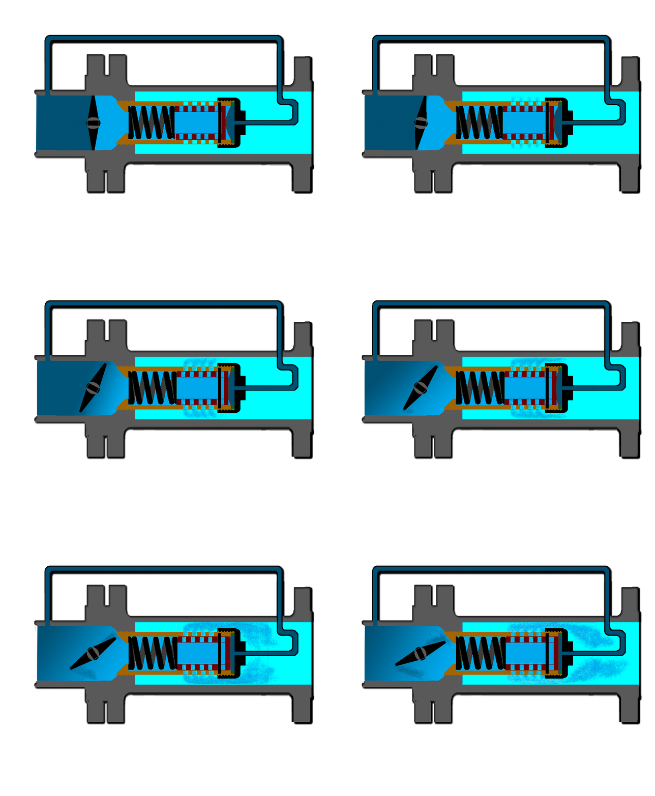
The graphic on the left shows how the VAD operates from fully closed to fully open.
Before pressure is introduced into the system, the spring force on the movable cylinder causes all of the holes to be open. But, when pressure is introduced to the upstream side of the throttling valve it also pressurizes the VAD's sensing chamber, which then overcomes the spring to close the VAD.
Then when the process controller signal causes the valve to open, pressure will also build-up inside the the main chamber, when added to the spring force, this will overcome the opposing force of the pressure in sensing chamber, which will cause the diffuser to open. Since this is a purely mechanical/fluid process, the pressure drop accross the modulating valve shall always be equal to that of the force of the spring.
As depicted in the animation, the control vane turns, and the upstream pressure (dark blue) begins to build-up pressure inside the sliding cylinder (light blue) which is assisted by the spring pressure. When the inside pressure plus the spring force overcomes the pressure in the sensing chamber, the inner cylinder will move to open the fixed diffuser holes in proportion to the imbalance of the forces.
The end result is that the VAD will automatically vary the area of its holes to maintain a constant 15 to 20 psi pressure drop across the control valve over its full operating stroke.

"Although complicated to describe, a VAD is a very simple device!"
VAD Dynamic Test: A 6" VAD set-up to verify flow capacity (Cv), Pressure Recovery (FL) Noise Attenuation (SPL), Operational Stability, and Response to changes in valve settings.
VAD without the upstream sensing line connected to its diaphragn chamber. In this test the VAD is wide open and, therefore functions as a fixed area diffuser. Note the cavitaion and noise being made when the 6" butterfly is about 1/2 open.
VAD with the upstream sensing line properly connected to the VAD's diaphragm chamber as it free discharges to atmosphere with 100 psi inlet pressure, demonstrating its responseiveness to changes in flow across the throttling butterfly valve. Note the stable flow stream, also less of cavitation and audible noise when the valve is less than 1/2 open.
VAD set-up to demonstrate the noise, cavitation, and turbulence caused when the sensing line to the VAD's diaphragn chamber is removed.This test demonstrates the VAD varying area technology by comparing the flow, turbulence and noise through a fixed area diffuser to the "Varying Area Diffuser".